TESSERACT SIGNATURE: A BRIEF DISCUSSION OF TECHNIQUE
Our goal was to create a high-resolution, high-energy, full range transducer…
Our goal was to create a high-resolution, high-energy, full range transducer that would both fully disappear within the soundstage it created and do so while preserving the humanity and emotion that is music. Technique should always be utilized in service to the sonic aesthetic. Regardless of the essential role new research played in developing the Tesseract Signature, we never lost sight of the aesthetic ideal.
The contextual mindset we have followed in arriving at a solution to each aspect of our investigation is that physical wave phenomena, whether optical, magnetic, or gravitational, all follow the same laws. For example, Maxwell’s partial differential equations are not only the foundational description of electromagnetism, but also of fluid dynamics, and with regard to tensor fields also govern gravitation and special relativity. In other words, it is possible to find a solution to each of our technical challenges through research into immutable physical principles.
TECHNICAL GOALS:
WIDEST POSSIBLE BANDWIDTH WITHOUT DISTORTION
A Flat amplitude response between 16Hz and 100 kHz. (‐3db points 13Hz and 70 kHz).
NO PHASE ERRORS
A new family of filter topologies were developed exclusively for this project based on classical all‐pass phase networks. These proprietary networks are more phase coherent in the cross band between drivers (minimum time ripple) with lower output in the stop‐band. Transducer phase coherence is vastly more complex than the elementary alignment of drivers in space according to their acoustic centers. Generating smooth lobing patterns in 3‐dimensional space requires blending of 2π to 4π radiation patterns with the intrinsic lobe output of the electrical network. Our proprietary networks maximize phase coherence by taking into account the variable radiation area of the piston, inter‐driver distance, and frequency at which the drivers cross. These new formulas dictate that driver filters will be idiotypically different within the array. Phase in this regard includes all distortive effects that compromise the presentation of time in a recording. Digital audio engineers are acutely aware of the bandwidth and transient response compromises inherent in brick‐wall filters vs. more sophisticated methods. The passage of time is an absolute constant; loudspeakers distort or destroy this invariant quantity more than any other component in the audio chain. Most loudspeakers do this poorly while some ignore the existence of time entirely.
NO GROUP DELAY DISTORTION
No phase errors are acceptable in the last octave between 32Hz
and 16 Hz. The goal of no low frequency phase errors and bandwidth below 16 Hz is not achievable with a vented box (phase deviation below cutoff frequency of the port) or a sealed box (impossible to generate low extension at full power without excessive rear cavity size). The only viable solution given the previous design constraints is a transmission line, bringing its own set of problems to be solved. Ripples in the pass‐band that obscure midrange harmonic structure must be eliminated. Aperiodic tapering and internal standing wave control are critical. The best musical blending of the TL with mid‐bass frequencies was achieved through our implementation of tempered scale tuning. The twelfth root of two or 12√2 is an algebraic irrational number which circumscribes the frequency ratio of a semitone in equal temperament in the Western musical scale. This principle was essential in separating standing nodes within the transmission line. In order to reach the low Q levels of the mid‐bass and midrange a high Bl product system had to be created. This was achieved by designing a custom driver with specific characteristics and utilizing it in an isobaric configuration. System Q is 0.5 with electronic manipulation of the lowest octave to give flat frequency and phase response. Electronic low pass filtering extinguishes any ripple in the pass‐band before it interferes with the output of the mid‐bass section. A 4.5 Kw amplifier is directly connected to the TL of each channel within the loudspeaker. All analog circuitry and automatic level sensing retain the sonic character of the amplifier utilized in driving the main frequency bandwidth. All circuitry is fully analog; no DSP signal manipulation or digital/analog conversion is employed anywhere in the system.
MINIMAL INTERMODULATION DISTORTION
This refers specifically to interactive distortion components between adjacent drivers in the array. Any vibrating surface adjacent to another vibrating surface will induce added “crosstalk” in the output pattern of each driver’s waveform, manifesting as intermodulation and doppler distortions. The solution is to use only the output of each plane in phase, extract any low level vibration from a driver not engaged in the full power output of the system and add specific physical planes to redirect uncorrelated energy. Inert physical cabinet structures are essential in achieving this goal; however no material or combination of materials is immune from vibrating. Excessive reverberations must be eliminated, while tertiary low level vibrations are harmonically integrated into the signal.
SHARP IMAGE EDGE DEFINITION WITHOUT FREQUENCY RESPONSE EXAGGERATION
Analog domain anti‐aliasing filtration eliminates excessive bandwidth from related overlapping wave generators. Noise outside the stop‐band must be specifically limited in order to eliminate the Moiré blurring effect at the edges of images. Proprietary analog filter technologies are applied to eliminate
this effect.
MAXIMUM AMBIENCE RETRIEVAL
Most hall ambience is ‐20 db from the fundamental tonal structure and often as low as ‐60 db. Any phase noise or intermodulation at high frequencies will obliterate this information. No break‐up modes are permitted in any driver, with special attention paid to flexion induced phase anomalies in the tweeter.
LOW NOISE FLOOR
Lost information within the filter network is common in all loudspeakers, hence the misguided idea that simpler networks are better. Poor components will exacerbate these losses in complex circuits. Our solution has been to create proprietary precision elements. These are low‐loss components with specific time constants (known number of micro seconds of storage time), precision resistance (no temperature dependent changes in resistance), and low hysteresis (minimized self‐inductance and low DC resistance through a wide bandwidth). With these component elements it is possible to design complexity into the circuit, conferring significant electrical control over driver output; this would be impossible in a simplistic control network.
MAXIMIZED DYNAMIC HEADROOM BY ELIMINATION OF CURRENT SATURATION EFFECTS
Pioneering technology in inductor and core design makes possible a 10 fold increase in current within the device before saturation effects are present.
MAXIMIZED TRANSIENT SPEED THROUGH CONSTANT Q AND VANISHINGLY LOW HYSTERESIS
Electrical signal contouring is combined through the previously enumerated techniques with careful matching of driver Vas, Bl product, and specifically shaped and damped driver cavities to produce a constant Q design. In this instance constant Q refers to minimal transient ringing at all frequencies within the array as well as keeping the Q consistent from driver to driver. This requires a sealed enclosure in some cases and a vented or transmission line enclosure in others. A new ceramic/honeycomb mid‐bass driver was custom designed for this purpose with an extremely high Bl magnetic structure in an underhung gap. Retaining a 0.5 Q in the warmth zone of the transducer is an essential quantity in maintaining transient speed and natural tonal timbre. New radial magnetic structures are employed in the midrange and tweeter with a combination of sealed transmission lines to continue the minimal ripple transient response concept.
POINT SOURCE FOCUS FOR REALISTIC IMAGE SIZING WITHOUT FREQUENCY DEPENDENT EXAGGERATION
SMOOTH AND EVEN POLAR RESPONSE
CONSTANT FIRST DERIVATIVE OF CROSS SECTIONAL RADIATION AREA
These three criteria are intertwined. In a multi‐driver array only a line source or point source driver arrangement are viable options for producing dispersion patterns which maintain a faithfulness to the original recorded information. The same is true of polar response. Without an open omni‐directional or open‐cardioid response, phase errors will enter the presentation post driver/cabinet interface. This problem is not resolvable through room treatment. The most common solution in elementary loudspeaker design is to use first order filters without any equalization in a large complex array. This non point source approach will inevitably produce huge overblown midrange images at the front of the stage and tiny anemic images at the back of the stage. This is a commonly ignored loudspeaker distortion, and one of the most obvious.
A smooth polar response brings evenness of image presentation across the soundstage, while careful attention to radiation area ads an important component to the previous discussion of image size. If an array is incorrectly balancing its surface area output, instruments or voices which should be small will appear large and vice versa.
PURELY PISTONIC MOTION THROUGHOUT THE PASS BAND
No driver break‐up modes in the passband are allowed; no soft diaphragms that intrinsically distort phase information while coloring harmonic structures with a specific artifact. This is a holdover from mistakenly conflating the driver behavior of a high‐end transducer with instrument amplification and sound reinforcement. In the “players world” we are always searching for specific desirable sounds and tonal colors we would like to hear from our instruments and amps. The best playback transducers should be faithfully reproducing the sound (from an amplified instrument, e.g. guitar) that the musician has determined through his choices, not by adding a specific sound of its own. The colorations of various instrument amps (Marshall vs. Fender vs. Hiwatt for example) are significantly due to the exitation of specific cone modes. This is unacceptable in high‐end reproduction. Tesseract Signature produces no phase error or driver break‐up down to ‐60 dB from the zero reference level.
SYMMETRICAL OVERALL IMPEDANCE CURVE FOR EASE OF DRIVABILITY; DRIVER DAMPING CIRCUITRY FOR PROPER LOAD INTERFACE
These criteria are addressed through a combination of physical driver damping and passive electrical elements which cancel voice coil inductance as well as back EMF. All drivers are considered equal in this, not just the woofers. These issues are essential to the loudspeaker/amplifier interface. By providing a benign load to the amplifier the best (and worst) qualities of the amplifier will be easily heard. We are all aware of loudspeakers which sound quite the same regardless of the amplifier or front‐end driving them. This blunt instrument approach is antithetical to our goal.
TOTAL ENERGY RADIATION IS CALCULATED OVER THE ENTIRE SURFACE OF THE LOBE NOT AT ONE MICROPHONE POSITION
Loudspeaker radiation patterns have intrinsic effects on distortion of the waveform being generated, as well as in‐room distortion effects from the loudspeaker interacting with the room itself. Judgment of waveform spread should be conducted as though measured from an infinite number of points around the transducer and integrated over the entire radiational area. Measuring from any single point (including the listening position) will not give an accurate representation of the actual energy spectrum which the listener experiences. Physically large loudspeaker arrays add another problem which is rarely considered by designers; how do we make such an imposing structure sonically disappear? Regardless of how well the initial signal from the transducer integrates with the listening environment, when energy returns from room boundaries to the loudspeaker cabinet, it will be “seen.” If a refrigerator shaped box is added to a room, even without making a sound of its own, it will be heard. Only by carefully designing a “stealth cabinet structure” through reversal of the radiation concepts discussed above will a large array sonically disappear in a listening environment.
More than 30 years of dedicated research into the specific physical and electrical phenomena of transduction has provided the foundation for our incomparable line of loudspeakers. Never before have all of these technical innovations and inventions been integrated into a high-energy audio transducer. This culmination of research, design, and aesthetic balance is Tesseract Signature.
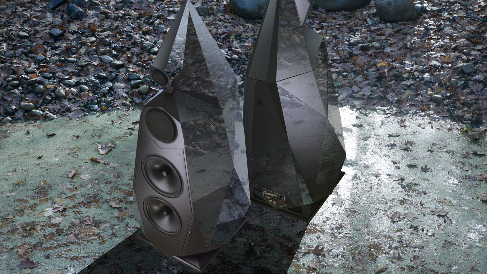
Tesseract
A four-dimensional hypercube.
An object from outside our 3-D world.
Sorry, the comment form is closed at this time.